How Electricity Works: Part 5: The Resistance

In the last post I talked about power, now let’s talk about how to figure out how much power a circuit uses. Pretty much any circuit out there can be thought of as being sort of like one big resistor. It has a resistance. The resistance of a circuit can vary depending on really anything we want it to vary on, but the same rules still apply: if we put a voltage across it, then:
[math]\latex {E =I*R}[/math]

Where E is the voltage, I is the current, and R is the resistance of the circuit. Remember: electrons are like rain drops falling from the sky. As they lose height (voltage) at a certain speed (current) they release energy over time. The amount of power they give off is equal to the height they start at (voltage) times the rate at which they lose it (current).

In other words:
[math]\latex { P=E*I}[/math]

Since
[math] \latex { \frac {E} {R} = I } [/math]
and [math] \latex { P=E*I} [/math]
then [math] \latex{P=\frac {E*E}{R}=\frac{E^2}{R}} [/math]

Isn’t math fun? If you’re as awesome as I am then you can just look at that formula and tell that the higher the resistance, the less power it will use (for a voltage source). If the resistance is too low then it will use a lot of power. In other words it will be pulling energy out at a fast rate. Where does that energy go? Well it depends on what kind of circuit this is, but if it’s just a plain old resistor then it’s being lost as heat, and if too much heat is coming out of it then it might explode.

All resistors have their own rating for how much power they can safely handle before they abuse it explode. But not to worry, we can protect it with another resistor.

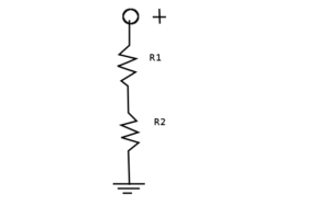
Like this:

voltage-divider

I’m the best at drawing stuff.  So R1 might be our big, bulky resistor, while R2 might be our small, wimpy one. To calculate how much power is going through each (since we’re so concerned about it) we just calculate the current going through each, and multiply it by the resistance across each one.

Since they’re in series that means that the current through both of them is the same, and that their resistances add up. So:

[math]\latex {I=\frac {V} {R1 + R2}}[/math]

And for the voltages: they’re the current multiplied by the voltage.

[math]\latex {V1=R1*\frac{V}{R1+R2}=V*\frac{R1}{R1+R2}}[/math]

This is known as the voltage divider rule. Note that for any number of resistors in series each one will be “dropping” a voltage (i.e. it will have a voltage across it), and that the voltages across all the resistors add up to V. Also note that the biggest resistor gets the most voltage, and therefore the most power.

To get the power we just multiply that by the current we calculate earlier (which is a long formula to write out).

How electricity works. Part 6: voltage and current sources.

One of the things that confused me about current was how batteries would specify a current on them even though the current is supposed to vary depending on the resistance based on ohm’s law.

So here’s how that actually works: there are two kinds of electrical power supplies: voltage sources, and current sources. Ideally voltage sources always offer the same voltage across them regardless of how little resistance you put across it, and ideally a current source will push the same current through a circuit regardless of how much resistance the circuit has.

If you place a really high resistance across a voltage source then the current going through the resistor will be low, an thus there will be very little power being used, and if you place a high resistance across a current source then the voltage across the resistor will be really high, while the current remains constant so it would be using quite a lot of power.

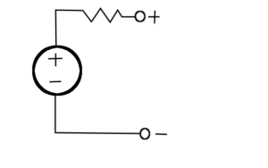
However in real life we don’t have ideal voltage and current sources. In real life voltage sources can be thought of as being like this:

real-voltage-source

As you can see a real voltage source is basically an ideal voltage source but with a resistor in series with it. This resistance is usually pretty low, but it means that if you short out the circuit then the voltage between the two terminals is zero. Also if you put too small of a resistance across it then the voltage goes down as the internal resistor of the voltage source is dropping almost all of the voltage.

If the current that your circuit is drawing is above the current that the power source specifies then that will blow up that resistor and/or the battery, or at the very least the voltage will drop.

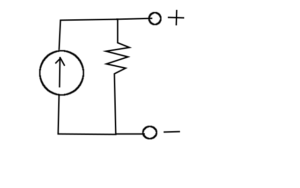
In addition to voltage sources having a secret resistor, current sources have one too.

real-current-source

Usually the internal resistance of a current source is pretty high. What this means is that if you put a resistor across its terminals that has too high of a resistance, then you won’t get very much current because more of that current can go through the internal resistor.

Every power source has these flaws. Whether they’re batteries, electrical outlets, power adapters, solar panels, or whatever other crazy sources of electrical energy we come up with.

How electricity works part 4: power

When most people hear the word power they probably think of this:

Or they might think of the idea of “energy”, but energy and power are actually two different things. Energy is defined as the ability to do “work” which in physics is a force that is done over a distance that is parallel to the force.

Basically: energy is the ability to do stuff. Power is the rate at which energy is transferred from one thing to another. Energy is measured in Joules, and power is measured in watts, and one watt is equal to one Joule being transferred per second.

This is relevant to electronics because electrical devices like light-bulbs have a rating telling you how much POWER it uses. A light-bulb that is left on overnight will use more energy than one that is left on for an hour, so the light-bulb manufacturers tell you how much power it will use, and let you figure out how much energy it will use given how long you want it to run.

They could probably tell you how much energy it will use, but that would imply that it was engineered to burn out after using a specific amount of energy, and that would be unethical. The power companies do however keep track of how much energy you’ve used. They keep track of it not in “joules” but in kilowatt-hours. Basically one thousand watts being used for one hour which is equal to 3.6 million joules (a joule is not a lot of energy).

It’s also important to understand that the power that a circuit uses is the current going through it multiplied by the voltage across it. So in other words the electrons are losing energy as they “fall”, and the voltage (or “height”) indicates how much energy they had initially, and the current (or “rate of falling”) indicates how quickly the energy from that electron is extracted and used for whatever you were hoping to do with it.

Therefore if you have a circuit with a low resistance, and you put a high voltage across it it will start to use a lot of power. This might not always be a bad thing though. Sometimes using a lot of power can be a good thing. If I built a machine for picking up big heavy boxes then I’d like the motors to be able to be able to use a lot of power so that it can pick up the heavy box more quickly. Or maybe I have a light-bulb, and I want it to be REALLY bright, so I want one that uses a lot of power because that means it can use a lot of energy very quickly for being bright.

It’s important to understand: efficiency is what’s important. I don’t want to buy a light-bulb that uses a lot of power yet doesn’t make a lot of light (presumably it just heats up a bunch). That would be a ripoff. Unfortunately the light-bulbs that can use a lot of power without dying tend to be very inefficient, while the light-bulbs that are really efficient can’t have a lot of power going through them or they die.

This is true of not just light-bulbs but pretty much everything. Machines that are powerful enough to move mountains tend to be inefficient at doing so.

How electricity works part 3: ohm’s law.

Because I didn’t understand voltage growing up I kind of rejected the idea of ohm’s law when I learned it because it didn’t make sense to me. I misunderstood voltage as being the rate that electrons flow through a wire, but apparently that’s what current is too?

Now I finally understand how it works: voltage is the “height” that the electrons are at, and current is the rate that they “fall down”. Current is measured in amps, and one amp is equal to one coulomb of charge going through the device per second.

Also pretty much everything has “electrical resistance” in addition to mass, charge, density, and those kinds of things. Whenever you put a voltage across some particular thing, the electrons will “fall down” through that material, and the rate of falling is the called the current.

The object that the current is going through is sort of like the atmosphere of a planet, I guess. It slows things down. Resistance is kind of like the thickness of that atmosphere. So when a voltage is placed across something, a current will pass through it, and the following formula will apply:

[math]$\begin{math}E=I*R$[/math]

where E is the voltage (short for “electromotive force” because obviously), I is the current, And R is the resistance. Many people get confused about the cause and effect here: “So putting a voltage across something causes the current to happen afterwards?” You might be saying to yourself, out loud, in a room full of people.

Try not to think of it as so much “cause and effect” but more as “any time there is a voltage across a resistance there will be a current, and any time there is a current going through a resistance there will be a voltage, and any time there’s a current traveling across a voltage there will be a resistance between the two”.

Basically the current and the voltage happen pretty much simultaneously. To fully understand this try playing around with the math to see how all of this works out with different resistances, currents, and voltages.

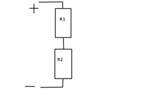
Here are a few handy things to keep in mind: if you have some kind of hypothetical electrical device that is supposed to have a resistance (like some kind of “resistor”) then placing two of them in series doubles the amount of resistor that the electrons have to fall through, and therefore doubles the resistance. The resistances add up when the are put “in series” like this:
series

Meanwhile putting them side by side with each other will cut the resistance in half because if the voltage across them is the same, then they each have the same amount of current going through each of them. This means that all together they have twice as much current going through this whole circuit than if there was only one of these things. Twice the current with the same voltage means half the resistance if you do the math.

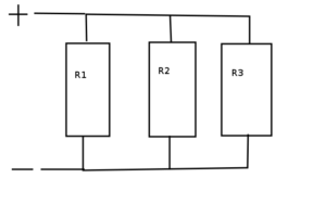
For any number of resistors “in parallel” like this the following rule will apply:

parallel

[math]$\Huge \begin{math}R=\frac{1}{\frac {1} {R1} + \frac {1} {R2} + \frac {1} {R3} + …}$[/math]

R is the total resistance of the circuit, and R1, R2, R3, and so forth are the resistors in parallel.
This means that as you add more resistors in parallel the resistance of the entire thing goes down. Adding something with a big resistance in parallel causes it to go down less than putting something with almost no resistance in parallel because math.

This is important because it means that although a single circuit (like just one resistor) might have a big resistance, and therefore not use much current, it can still be a part of a much bigger circuit that has a lot of parts, and therefore, as a whole, has very little resistance and uses a lot of current.

So in other words all circuit have a resistance, and will have a current going through them when a voltage is placed across them, and the same is true for any circuit that this circuit is made of.

Note that the resistance that a circuit has can change, and so can the current going through it, and the voltage across it; however ohm’s law will always be true for that circuit no matter what the situation.

How electricity works. Part 2: voltage

When I was growing up I would often read through a bunch of explanations on electricity that always described voltage as “being like electrical pressure”. Now I understand what voltage is, and I still have no clue what that was supposed to mean. Here’s what voltage actually is, but first an analogy:

Electrical charge is sort of like gravity. If you have a positive charge and a negative charge, and hold them some distance away from each other there will be potential energy stored in the distance they are from each other. They want to go to each other, to hold that charge in her arms and say “I love you” before they kiss and the credits role, but sadly the charges cannot meet as cruel fate (i.e. me trying to explain something) is holding them back, but as soon as I let go then all of that potential energy will become kinetic energy as they smash into each other.

Since charge is like gravity, we can use gravity as an analogy for things. If you have a ball that you’re holding in the air then the ball “wants” to go down. The ball has potential energy which is equal to its weight times the height it is at. We can describe the potential for potential energy from gravity at any point in the universe by multiplying the pull of gravity at that point by that points height.

On Mars there’s some point off the ground where you could have precisely: a lot of energy if you were to drop a bowling ball from that height, but you’d have a lot less energy if it was a tennis ball. What I’m talking about is a number that you multiply by the mass of the object in question to get the amount of potential energy it would have if it was held at that point, which is a great way of measuring how dead you would be if you fell from that point. This hypothetical measurement could be taken at any point around any planet.

Why is this relevant? Because we have this exact sort of thing with charge. It’s called “voltage”. Voltage is the amount of potential energy at a point per the amount of charge you could put at that point.
Five volts is equal to five joules of energy for every coulomb you could put there.

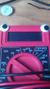
Now that I’ve explained that it’s time to introduce you to Mr. Multimeter:
IMG_20150708_165905

This is Mr. Multimeter. As you can see he has googly eyes because of course he does. Mr. Multimeter has two wires that come off of him. One of these wires is black, and the other is red. Mr. Multimeter can measure the voltage between these two wires. Let that sink in for a second. That might sound like it doesn’t make sense, but consider this:

If we have a hot air balloon that’s a kilometer up, then it’s a kilometer up from the ground. That’s what people mean when they say “5000 feet in the air”. They are measuring feat from the ground and not the center of the Earth. In other words: height is relative. Much the same voltage is relative.
Mr. Multimeter measures voltage from the “ground” (i.e. the black wire) to whatever voltage is at the red wire.

When a circuit makes “5 volts” at one of its outputs it makes it 5 volts from the ground. If two circuits don’t have the same “ground” (i.e. they are at different “heights”) then 5 volts to one circuit is a different voltage to another circuit; however hooking their grounds together makes them the same ground.

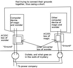
That said here’s a word of warning: be careful about hooking the grounds together of two things that both plug into a wall for energy. Often the ground of one device can be traced directly back to one of the metal prongs on the plug that goes into the wall.

Here’s a crudely drawn illustration made with professional image editing software to help explain:
the-grounding-problem-explained

Most devices that the normals use don’t connect their “grounds”. As such many of the AC to DC converters they use just hook the ground of the device directly up to the outlet. So if two grounds are connected for two things that plug into a wall then you might short out the electrical outlet.

How electricity works. Part 1: charge

After checking through the posts I’ve made I found out that I haven’t yet explained one of the things that most
confused me growing up: electricity. So I will be attempting to explain how electricity works in a way that I think might be more helpful.

First let’s talk about charge.
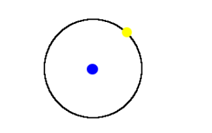
When people hear the word “atom” they probably think of this:
atom

“You’ve got your proton in the center, and your electron orbiting around it, and the proton has a positive charge, and the electron has a negative charge.” -Every teacher ever.

“Wait, am I supposed to know what this “charge” thing is? ” -My thoughts when I heard this as a child.

Charge is sort of like mass. All things in the universe have mass. If you have something in front of you then that has mass, and density, and volume, and a bunch of other things that describe it. Mass, and density, and volume aren’t things that exist inside of something (or at least I don’t think they do) they are properties OF that thing, and the same can be said of charge.

All things have a charge, but unlike mass, and volume, and density, the charge of an object can not only be zero, but it can be negative. Most objects we usually deal with have little to no charge because the world ordinary people live in is boring, and by extension they are too. because then things would be flying all over the place all the time.

Here’s some facts about charge:
*The standard unit for charge is the coulomb.
When two positively charged objects are close to each other one will be pushed away with a force equal to this:

[math]$\begin{math}F=K*\frac{Q1*Q2}{r^2}$[/math]

K is coulomb’s constant, Q1 is the charge of the first object, Q2 is the charge of the second object, and r is the distance between their centers. It’s a lot like Newton’s formula for gravitation, except that the constant is way higher.

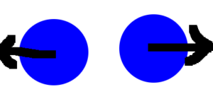
The first object will feel this force pushing it away from the second object, and the second object will have the equal and opposite force pushing it the other way as depicted in my crudely drawn diagram:

Two blue circles with black arrows that point outwards.

The same is true for two negatively charged objects, and a positive object will be attracted to a negative object with the same force, and vice versa.

So in other words: like objects repel, and unlike items attract.

How I Made A Wheely Robot.

So far I’ve had a policy of only making updates when I’ve completed a project, but instead I’m going to post an update of a project that’s still in progress since it would take so long to finish. Introducing: the wheely robot.
20160515_220806
Note that I’m not exactly the best photographer yet, but at least you can figure out that it’s a robot.

So what does it do? Well so far I’ve been working on it as a sort of experiment on how to program robots.
A problem that I’ve run into before with earlier attempts at building robots was that I might tell the robot to move forward some distance (like for example: one meter), and it would move forward, but if something was in the way, or its wheels didn’t get as much traction as it thought it was getting then it would stop too soon, and not realize that it hadn’t actually reached the goal.

The problem at its core was that the earlier robots weren’t aware of the kinds of the fact that when they try to do something, that thing might not have actually gotten done because of some kind of obstacle. That’s where the fancier kinds of programming come into play.

The first fancy programming trick is what’s called a “PID controller”. The idea is pretty simple: the robot tells its wheels to move forward at speed x, and there are sensors at the wheels that tell the robot how fast its wheels are ACTUALLY moving, and then that data goes to the computer which uses an algorithm known as the “PID controller” that adjusts to any variations in speed.

More info here:
https://youtu.be/ZhYi7x0rMoE?list=PLkHsKoi6eZnx9zMNsvL9ni7–2Lvyb88d

This is a pretty simple way to adapt to problems, my robot uses wheel encoders to figure out where the wheels are, and they aren’t a very good way to get sensor feedback which is why I’m working on getting more sensors for it.

I’ve also added multiple computers onto it. One handles sensor data since there will be so many sensors on the robot in the future, and one controls everything. The two communicate via i2c. With fancier programming techniques I could someday get it to use behavior-based robotics to go around obstacles (more info here, and here).

I’m also keeping a github repo for it here which will hopefully have some useful info (note: I’ve made changes to it recently which I haven’t tested). I’ve also setup an amazon wish-list here that has (almost) all the parts I used (it as of this writing doesn’t contain the screws that I used to screw everything in).

I’m hoping to someday make this go throughout my apartment and pick up things off the floor for me before a vacuum robot goes through.

How to hide secret messages in an image.

If you haven’t seen it yet: here‘s a little challenge I put together on my twitter page to see if people can find the
secret message in a pair of pictures. If you want to try cracking it then don’t read further because I’m about to tell the secret to it.

Here‘s a video about hiding secret messages within pictures that explains the basic idea, and here is the tutorial I followed to hide the image (and how to extract it).

The trick is to set the last bit of every pixel to one of the bits for the hidden message. Most people wouldn’t
notice because flipping the last bit of a pixel only changes its color value by one, and most people won’t notice such a small color change, especially for a picture with a lot of color noise.

The advantage to this method is that it works in Gimp (and possibly Photoshop, I haven’t tested it), but you can only insert non-encrypted images.

Finally here is the link to the answer.